Browsed by
Category: Computer Projects

Computer projects I’m working on

WIP: Cantenna

WIP: Cantenna

This shows step by step how I made a Cantenna. This is a simplified tl;dr version of “How to build a tin can waveguide antenna” by Gregory Rehm.

Materials:

  • 1x Can, washed (hapi HOT Wasabi Peas [450g])
  • 1x N-type, Female Chassis-mount connector (Digikey# 367-1081-ND)
  • 1x Piece of copper wire
  • 4x Nuts & bolts

Prep:

  1. Measure diameter of the can -> 3.9″
  2. Calculate wavelength using waveguide calculator found here.
  3. Mark a point 1/4 Wavelength up from the bottom (closed) side of the can.
  4. Measure the hole to be cut (diameter of part of the connector that will be going inside the can) -> 0.43″
  5. Drill marked point to measured diameter (0.43″)
  6. Dry-fit the connector, and mark holes for the screws or nuts/bolts (if any)
  7. Drill marked points to the diameter of your connector’s holes (if any)
  8. Cut a piece of copper wire so that when it is in the copper sleeve on the connector, the total length of the copper sleeve and piece of copper is exactly 1.21″ (or as close as you can humanly get to it), and solder it in place.
  9. Mount the connector in the hole in the can and secure it with screws or nuts/bolts (if any). Make sure to mount the heads of the screws or bolts inside the can to reduce antenna obstruction.
EVEm V1.1 Carputer

EVEm V1.1 Carputer

I scored a mega-deal on eBay a while back for this EVEm mini-ITX computer with an EVEm DC/DC power supply, in a generic mini-ITX case.

The EVEm has a VIA C3 Samuel2 600MHz “1GigaPro” CPU and a VIA VT133 Chipset.

I added the specified maximum of 256MB of 133Mhz SDRAM, and am currently using a 3.5″ 6.4Gb hard drive.

For more stats, look in this forum thread and in the English Manual. The support site can be found here.

The DC/DC Power supply is based on the Texas Instruments TL1451A.

When Good Caps Go Bad

When Good Caps Go Bad

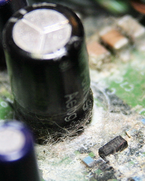
When this 0.22 Farad, 2.5 Volt super capacitor’s time came, it didn’t go easily. It put up a fight: It let all of its electrolyte out through its bottom and onto the PCB, leaving a hard, crusty layer, and a capacitor that doesn’t work.

It is typically used in place of a standard “battery backup”, and possibly to retain RAM contents between short resets.

Part Specs:
Manufacturer: Cooper Bussmann
Type: PowerStor Aerogel Type B, 0.22F 2.5V Capacitor

Digikey Part Number

WRTSL54GS Hardware & Architecture

WRTSL54GS Hardware & Architecture

Here’s the dump of /proc/cpuinfo:

# cat /proc/cpuinfo
system type             : Broadcom BCM4704 chip rev 8
processor               : 0
cpu model               : BCM3302 V0.6
BogoMIPS                : 263.78
wait instruction        : no
microsecond timers      : yes
tlb_entries             : 32
extra interrupt vector  : no
hardware watchpoint     : no
VCED exceptions         : not available
VCEI exceptions         : not available

Here’s the dump of /proc/interrupts:

# cat /proc/interrupts
           CPU0
  2:      26752            MIPS  eth2, ehci_hcd
  3:        223            MIPS  serial
  4:       2476            MIPS  eth0
  7:      95322            MIPS  timer
ERR:          0

Here is the dump of /proc/pci:

# cat /proc/pci
PCI devices found:
  Bus  0, device   0, function  0:
    Class 0501: PCI device 14e4:0800 (rev 8).
      IRQ 3.
      Non-prefetchable 32 bit memory at 0x18000000 [0x18000fff].
      Non-prefetchable 32 bit memory at 0x1fc00000 [0x1fffffff].
      Non-prefetchable 32 bit memory at 0x1c000000 [0x1dffffff].
      Non-prefetchable 32 bit memory at 0x1a000000 [0x1bffffff].
  Bus  0, device   1, function  0:
    Class 0200: PCI device 14e4:4713 (rev 8).
      IRQ 4.
      Master Capable.  Latency=64.
      Non-prefetchable 32 bit memory at 0x18001000 [0x18001fff].
  Bus  0, device   2, function  0:
    Class 0200: PCI device 14e4:4713 (rev 8).
      IRQ 5.
      Master Capable.  Latency=64.
      Non-prefetchable 32 bit memory at 0x18002000 [0x18002fff].
  Bus  0, device   3, function  0:
    Class 0c03: PCI device 14e4:4715 (rev 8).
      IRQ 6.
      Non-prefetchable 32 bit memory at 0x18003000 [0x18003fff].
  Bus  0, device   4, function  0:
    Class 0604: PCI device 14e4:0804 (rev 8).
      IRQ 2.
      Non-prefetchable 32 bit memory at 0x18004000 [0x18004fff].
      Non-prefetchable 32 bit memory at 0x8000000 [0xfffffff].
  Bus  0, device   5, function  0:
    Class 0b30: PCI device 14e4:0816 (rev 8).
      IRQ 2.
      Non-prefetchable 32 bit memory at 0x18005000 [0x18005fff].
  Bus  0, device   6, function  0:
    Class 0703: PCI device 14e4:4712 (rev 8).
      IRQ 2.
      Non-prefetchable 32 bit memory at 0x18006000 [0x18006fff].
  Bus  0, device   7, function  0:
    Class 1000: PCI device 14e4:4718 (rev 8).
      IRQ 2.
      Non-prefetchable 32 bit memory at 0x18007000 [0x18007fff].
  Bus  0, device   8, function  0:
    Class 0500: PCI device 14e4:080f (rev 8).
      IRQ 3.
      Non-prefetchable 32 bit memory at 0x18008000 [0x18008fff].
      Non-prefetchable 32 bit memory at 0x0 [0x7ffffff].
      Non-prefetchable 32 bit memory at 0x10000000 [0x17ffffff].
      Non-prefetchable 32 bit memory at 0x80000000 [0x9fffffff].
  Bus  1, device   0, function  0:
    Class 0600: PCI device 14e4:4704 (rev 0).
      IRQ 2.
      Master Capable.  Latency=64.
      Non-prefetchable 32 bit memory at 0x40000000 [0x40001fff].
      Prefetchable 32 bit memory at 0x0 [0x7ffffff].
  Bus  1, device   1, function  0:
    Class 0280: PCI device 14e4:4318 (rev 2).
      IRQ 2.
      Master Capable.  Latency=64.
      Non-prefetchable 32 bit memory at 0x40002000 [0x40003fff].
  Bus  1, device   2, function  0:
    Class 0c03: PCI device 1033:0035 (rev 67).
      IRQ 2.
      Master Capable.  Latency=8.  Min Gnt=1.Max Lat=42.
      Non-prefetchable 32 bit memory at 0x40004000 [0x40004fff].
  Bus  1, device   2, function  1:
    Class 0c03: PCI device 1033:0035 (rev 67).
      IRQ 2.
      Master Capable.  Latency=8.  Min Gnt=1.Max Lat=42.
      Non-prefetchable 32 bit memory at 0x40005000 [0x40005fff].
  Bus  1, device   2, function  2:
    Class 0c03: PCI device 1033:00e0 (rev 4).
      IRQ 2.
      Master Capable.  Latency=68.  Min Gnt=16.Max Lat=34.
      Non-prefetchable 32 bit memory at 0x40006000 [0x400060ff].
Parts from Digi-Key!

Parts from Digi-Key!

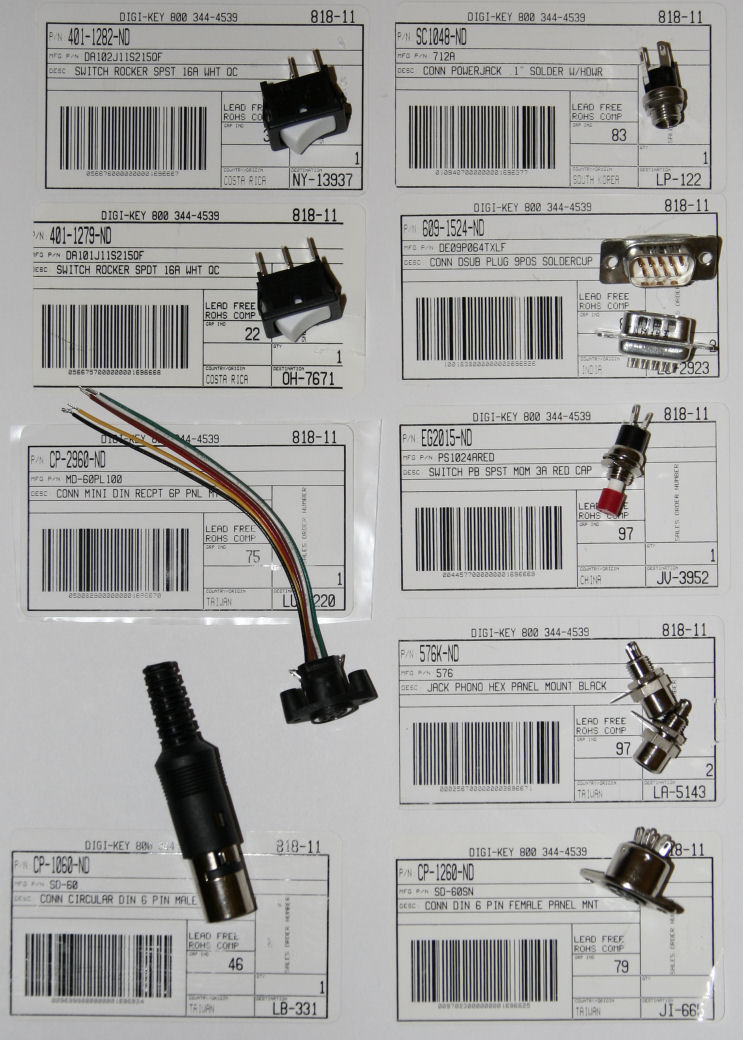
Ok, here’s the batch of parts I received from Digi-Key for my C64 DTV.

I ordered case-mount parts so I wouldn’t have to worry about making boards to mount the connectors.

CP-1060-ND – 6-Pin DIN Male Connector (Tested to fit into C64 IEC port)
CP-1260-ND – 6-Pin DIN Panel-Mount Female Socket (Mates with CP-1060-ND)
609-1524-ND – 9-Pin DSUB Male Plug with Solder Cups
CP-2960-ND – 6-Pin Mini-DIN Panel-Mount Female Socket
576K-ND – Phono Jack, Black Center, Panel Mount with Hex nut and Hex base

401-1282-ND – SPST 16A Rocker Switch (White Rocker on Black Housing)
401-1279-ND – SPDT 16A Rocker Switch (White Rocker on Black Housing)
EG2015-ND – Momentary 3A SPST Pushbutton Switch with Solder Loop Pins (Red Cap and White Stem)

SC1048-ND – 0.1″ Panel-Mount Power Jack Connector, Solder Loop Pins, with Hardware

MSNTV2 Close-up

MSNTV2 Close-up

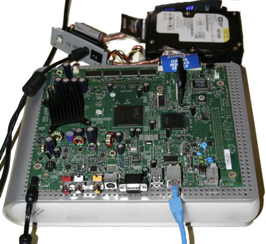
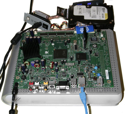
MSNTV2 with IDE, Serial header and Power.

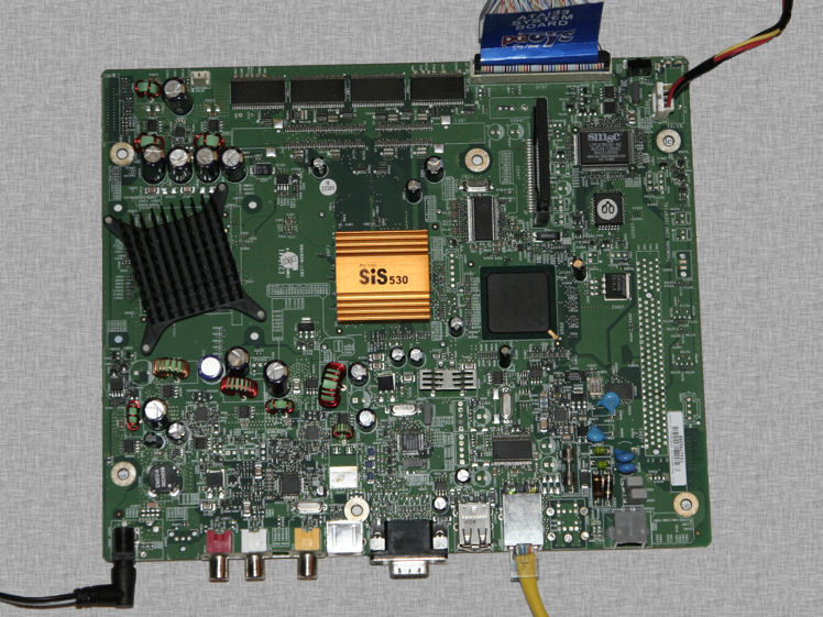
Here’s a better shot of the MSNTV2. Note: I added an old heatsink  to the Northbridge, as it tends to run warm.

:thumbsup:

MSNTV2 Hardware & Architecture

MSNTV2 Hardware & Architecture

Here’s what phpSysInfo has to say:

Processors  	1
Model 	Mobile Intel(R) Celeron(TM) CPU 733MHz
CPU Speed 	731.08 Mhz
Cache Size 	256.00 KB
System Bogomips 	1445.88
PCI Devices 	
-	Ethernet controller: Intel Corporation 82801DB PRO/100 VE
-	Host bridge: Intel Corporation 82830 830 Chipset Host Bridge
-	IDE interface: Intel Corporation 82801DB
-	ISA bridge: Intel Corporation 82801DB/DBL
-	Modem: Intel Corporation 82801DB/DBL/DBM
-	Multimedia audio controller: Intel Corporation 82801DB/DBL/DBM
-	PCI bridge: Intel Corporation 82801 PCI Bridge
-	SMBus: Intel Corporation 82801DB/DBL/DBM
-	(3x) USB Controller: Intel Corporation 82801DB/DBL/DBM
-	USB Controller: Intel Corporation 82801DB/DBM
-	VGA compatible controller: Intel Corporation 82830 CGC [Chipset Graphics Controller]
IDE Devices 	
-	hda: SanDisk SDCFB-64 (Capacity: 61.25 MB)
-	hdc: WDC WD1600JB-00GVC0 (Capacity: 149.05 GB)
SCSI Devices 	none
USB Devices 	none

Here’s the dump of /proc/cpuinfo:

$ cat cpuinfo
processor       : 0
vendor_id       : GenuineIntel
cpu family      : 6
model           : 11
model name      : Mobile Intel(R) Celeron(TM) CPU          733MHz
stepping        : 4
cpu MHz         : 731.087
cache size      : 256 KB
fdiv_bug        : no
hlt_bug         : no
f00f_bug        : no
coma_bug        : no
fpu             : yes
fpu_exception   : yes
cpuid level     : 2
wp              : yes
flags           : fpu vme de pse tsc msr pae mce cx8 mtrr pge mca cmov pat pse36 mmx fxsr sse
bogomips        : 1445.88

An explaination of what the flags are is available here: IntelĀ® 64 and IA-32 Architectures Software Developer’s Manuals in Volume 2: Instruction Set Reference, specifically pages

3-172

to

3-176

of Volume 2A: Instruction Set Reference

Here is the output of lspci on an MSNTV2:

$ lspci -tvv
-[00]-+-00.0  Intel Corporation 82830 830 Chipset Host Bridge
      +-02.0  Intel Corporation 82830 CGC [Chipset Graphics Controller]
      +-1d.0  Intel Corporation 82801DB/DBL/DBM (ICH4/ICH4-L/ICH4-M) USB UHCI Controller #1
      +-1d.1  Intel Corporation 82801DB/DBL/DBM (ICH4/ICH4-L/ICH4-M) USB UHCI Controller #2
      +-1d.2  Intel Corporation 82801DB/DBL/DBM (ICH4/ICH4-L/ICH4-M) USB UHCI Controller #3
      +-1d.7  Intel Corporation 82801DB/DBM (ICH4/ICH4-M) USB2 EHCI Controller
      +-1e.0-[01]----08.0  Intel Corporation 82801DB PRO/100 VE (CNR) Ethernet Controller
      +-1f.0  Intel Corporation 82801DB/DBL (ICH4/ICH4-L) LPC Interface Bridge
      +-1f.1  Intel Corporation 82801DB (ICH4) IDE Controller
      +-1f.3  Intel Corporation 82801DB/DBL/DBM (ICH4/ICH4-L/ICH4-M) SMBus Controller
      +-1f.5  Intel Corporation 82801DB/DBL/DBM (ICH4/ICH4-L/ICH4-M) AC'97 Audio Controller
      \-1f.6  Intel Corporation 82801DB/DBL/DBM (ICH4/ICH4-L/ICH4-M) AC'97 Modem Controller

Here’s the dump of /proc/ioports:

$ cat /proc/ioports
0000-001f : dma1
0020-0021 : pic1
0040-0043 : timer0
0050-0053 : timer1
0060-006f : keyboard
0070-0077 : rtc
0080-008f : dma page reg
00a0-00a1 : pic2
00c0-00df : dma2
00f0-00ff : fpu
0170-0177 : ide1
01f0-01f7 : ide0
02f8-02ff : serial
0376-0376 : ide1
03c0-03df : ega
03f6-03f6 : ide0
03f8-03ff : serial
0500-053f : 0000:00:1f.0
0cf8-0cff : PCI conf1
1000-107f : 0000:00:1f.0
8000-801f : 0000:00:1d.0
8020-803f : 0000:00:1d.1
8040-805f : 0000:00:1d.2
9000-903f : 0000:01:08.0
  9000-903f : e100
a020-a02f : 0000:00:1f.1
a040-a05f : 0000:00:1f.3
a100-a1ff : 0000:00:1f.5
a200-a23f : 0000:00:1f.5
a300-a3ff : 0000:00:1f.6
a400-a47f : 0000:00:1f.6

Here’s the dump of /proc/interrupts:

$ cat /proc/interrupts
           CPU0
  0:   32149675          XT-PIC  timer
  2:          0          XT-PIC  cascade
  4:        169          XT-PIC  serial
  5:    6825495          XT-PIC  eth0
  8:          2          XT-PIC  rtc
 14:         87          XT-PIC  ide0
 15:   14329233          XT-PIC  ide1
NMI:          0
LOC:          0
ERR:          0
MIS:          0

Update:

Probing for `SMSC 47M15x/192 Super IO Fan Sensors'
Success... found at address 0x0800

It looks like the fan controller is an SMSC 47M1, meaning you can control and monitor fan speed using programs such as lm-sensors. Here is the doc file for the SMSC 47M1.

MSNTV2 Boot Tutorial

MSNTV2 Boot Tutorial

Well, it’s 3AM, but I got my first MSNTV2 server running using linux kernel 2.6.12.5, so here’s a writeup on how it’s done.

This is provided with no guarantee of accuracy or completeness

This tutorial assumes the following:

  • You will be installing a hard drive into the MSNTV2 box via an IDE cable.
    • (The process for a USB drive is similar, with the exception that you must compile the kernel as such to be able to boot from USB, and you must append rootwait=10 to the CMDLINE file)
  • You have soldered an IDE header onto the MSNTV2 motherboard
  • You have already patched the BIOS of the MSNTV2 (See “Getting into the service menu” and “Flashing the patch” on the Toc2rta Wiki
  • You already have a CompactFlash card prepared as detailed in the Toc2rta Wiki, with:
    • a CMDLINE file (root=/dev/hdc3 init=/sbin/init console=ttyS0,115200)
    • BIOS.BIN (You’ll have to search Google for it)
    • (We will be compiling the VMLINUX.BIN in this tutorial)
  • You are currently using the hard drive you wish to install into the MSNTV2. It currently has:

Note: The CompactFlash card is known as /dev/hda to the MSNTV2 box. Once the drive is installed into the MSNTV2, it will be known as /dev/hdc (If the drive has no jumpers present) or /dev/hdd (If jumpered as ‘slave’).

For those trying to compile it for themselves, and for myself for later reference:

  1. Download linux-2.6.12.5.tar.gz
  2. Move linux-2.6.12.5.tar.gz to /usr/src/ (mv linux-2.6.12.5.tar.gz /usr/src)
  3. Change directories to /usr/src/ (cd /usr/src)
  4. Extract linux-2.6.12.5.tar.gz into /usr/src/ (tar -xvf linux-2.6.12.5.tar.gz)
  5. Add the .config file:
    1. Download the attachment to this article
    2. Change directories to where the attachment was downloaded (Example: cd ~/Desktop/)
    3. Copy it to the /usr/src/linux-2.6.12.5/ folder and rename it to .config (cp msntv2-config-2.6.12.5 /usr/src/linux-2.6.12.5/.config)
  6. Make the kernel and modules:
    1. Change directories to /usr/src/linux-2.6.12.5 (cd /usr/src/linux-2.6.12.5)
    2. Make sure the source code has no temporary files, etc (make clean)
    3. Build the Kernel (make)
      1. If you are prompted whether or not to include an item that was not included in the .config, just press Enter, and it will select the default recommended setting.
    4. Install the modules (make modules_install)
  7. Copy the vmlinux.bin to the first partition of your CF card.
    1. Mount your CF card if not already done. Note: Many GUIs will do this for you. The mounted path and device may vary. (Example: mount /dev/sda1 /media/sda1)
    2. Copy the vmlinux.bin from /usr/src/linux-2.6.12.5/arch/i386/boot/compressed/vmlinux.bin to the first partition of your CF card. (Example, assuming a USB card reader mounted to /media/sda1: cp /usr/src/linux-2.6.12.5/arch/i386/boot/compressed/vmlinux.bin /media/sda1/) 
  8. Edit your /etc/fstab file: (See attachments for an example of a modified fstab)
    1. Change any references of /dev/hda to /dev/hdc
    2. Remove or comment out any /dev/cdrom entry
    3. [Experimental, for me at least] Add an entry for the first partition of the CompactFlash (/dev/hda1 none vfat defaults 0 0)
  9. Install this hard drive onto the MSNTV2 using an EIDE ribbon cable.

Picture of my current setup: