Browsed by
Category: Electronics Projects

My Electronics Projects

FT4232H-Based Eee 701 Internals Controller

FT4232H-Based Eee 701 Internals Controller

Attachment: Schematic PDF

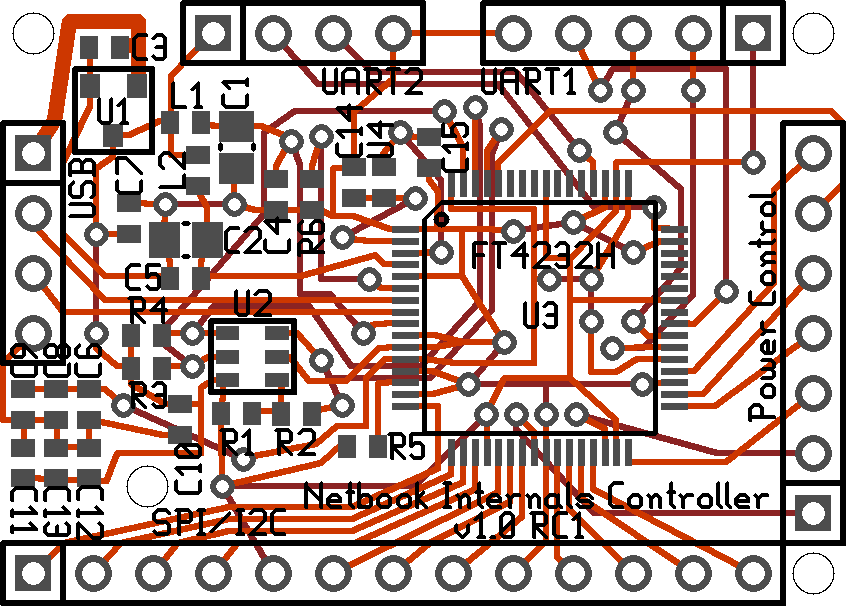
This controller will be designed for installation into an Eee 700-series netbook to serve the following purposes:

  1. Provide a communications interface to I2C, SPI and UART devices over USB
  2. Control power switching to various internally-mounted low-current (~0-25mA) and high-current (~25-125mA) devices.
  3. Provide non-USB-Host 5V power to the high-current USB devices through high-current SPST switches so as not to overload the USB Bus (Update: This will be done by off-board MOSFETs. There just wasn’t enough room on the board to allow it to still fit in the space allocated for the MDC1.5.

Requirements:

  • The finished PCB should fit comfortably inside an Eee 700-series netbook, in the MDC1.5 spot (A modem was planned for the Eee 700-series, but never released. There is an empty space in the Eee 700-series case to fit a Mobile Data Card (Modem), but one was never included, and the option was removed from later BIOSes. In later netbooks the connector was no longer soldered in.)
  • The finished PCB will have through-hole connectors for attaching external devices, USB, external power, etc. for ease of soldering and to help prevent solder-pad lifting.
  • Surface-mount parts will be used to save space (I know, they’re a pain to solder. I don’t look forward to it, but there just isn’t a whole lot of room inside the Eee)
  • It would be nice to have all pins aligned at 0.1″ so it could be put on a breadboard for prototyping.

Background:

This came about in its current form through discussions on #sparkfun as I was looking for a controller to go along with devices such as GPS that I would (hopefully) purchase on SparkFun’s Free Day. I was stuck between the Arduino Pro Mini and the Mini Bully to allow for SPI communication; however, I would still have had to include a USB-TTL FT232R-based converter. It was suggested that I use the FT2232 since I could do SPI and UART on the same chip.

Unfortunately, or fortunately (depending on how you look at it), I looked again at the size of the USB-capable GPS I wanted (GS407), and found that there was no way it was going to fit, despite my previous measurements. I instead chose the Venus GPS with SMA for its size; however, it has a UART interface, and I was stuck now with SPI and UART devices (And maybe some I2C). This is why I’m looking now at the FT2232H and the FT4232H (Which is pin-identical to the FT2232H, just with 4 ports instead of 2).

FTDI Chips:

FT2232D:

The FT2232D has 2 channels and is slightly smaller and takes less than half the power of the newer FT2232H, but the FT2232D only allows for one MPSSE (Multi-Protocol Synchronous Serial Engine: the encoder that allows you to use I2C, SPI, etc.) channel. This means you can have one JTAG, I2C or SPI channel. Channel 2 (Also called B) doesn’t support the MPSSE engine; it is only for RS232 UART, RS245 or other serial modes.

FT2232H:

The FT2232H is larger than the FT2232D, and consumes more than double the current. However, the FT2232H supports MPSSE on both of its 2 channels: You can now have SPI, I2C, RS232 UART, etc in any configuration. It has a direct upgrade path to the FT4232H thanks to a shared size, footprint and power requirements.

FT4232H:

The FT4232H is a direct replacement for the FT2232H, and allows for 4 channels instead of 2. The MPSSE can be used on channels A and B simultaneously. Though the number of channels goes up for the FT4232H, the number of supported protocols goes down; however, this chip supports all of the protocols this project would ever require: UART, SPI, I2C and maybe bit-banging. This project has no plausible requirement for RS245, FIFO, Host Bus Emulation or the like.

FT4232H Channels:

  1. RS232 UART, JTAG, SPI, I2C or bit-banging
  2. RS232 UART, JTAG, SPI, I2C or bit-banging
  3. RS232 UART or bit-banging
  4. RS232 UART or bit-banging

Ports: Here’s what I personally plan to attach on each of the ports of my copy of the project board.

Channel A: SPI #1

  • 3-Axis Accelerometer (Has an optional interrupt for motion detection. Has buffer room for 64 samples per axis. Supports reading of its 9-bit temperature sensor over the serial bus.)
  • Cable Select for each SPI device on GPIOs.
  • Interrupt from 3-Axis Accelerometer, if needed

Channel B: I2C or SPI #2

  • Sensors: Temperature, …?
  • FM Radio Receiver AR1010

Channel C: UART #1

  • Venus 634FLPx GPS (I’ll have to see what this GPS supports in regards to buffering to see if it could handle being on the SPI bus along with the accelerometer.)

Channel D: UART #2

  • Kenwood D7A APRS In or GPS Location Out

GPIOs: (Spare pins on Channels A or B)

  • Triggers for high-current SPST Switches or MOSFETs for switching power to internal devices
  • LED(s)?

Voltages: Voltage requirements of each device I intend to connect

  • FM Receiver AR1010: 3.3V
  • 3-Axis Accelerometer SCA3000: 3.35V-10V
  • Venus 634FLPx GPS: 2.7V-3.3V
  • FT4232H or FT2232H: 3.3V

Amperages Required and Equivalent Current Draw at 5V: 5V Current Equivalents for determining if all devices specified can be safely run on USB power or if they would require power from another source. (These are based on rough figures, and are always subject to the device’s operating conditions. I just want to see if it’s in the ballpark)
AR1010:
(Max current 16mA at 3.3V, as per module datasheet.)

  • 3.3 Volts * 0.016 Amps = 0.0528 Watts
  • 0.0528 Watts / 5 Volts = 0.01056 Amps
  • 0.01056 Amps = 10.56 milliamps at 5V

SCA3000: (Typical current during motion capture of 650uA at 3.3V, as per chip datasheet)

  • 3.3 Volts * 0.00065 Amps = 0.002145 Watts
  • 0.002145 Watts / 5 Volts = 0.000429 Amps
  • 0.000429 Amps = 0.429 milliamps at 5V (== 429uA at 5V)

Venus 634FLPx GPS: (Typically 28mA at 2.7-3.3V in tracking and navigation mode, per chip datasheet. A commenter on the Sparkfun product page notes that the added LED will add an extra 10mA (when the LED is turned on), so I’m going to go with 38mA for now. I’m going to assume their rated current is at the higher of the range: 3.3V)

  • 3.3 Volts * 0.038 Amps = 0.1254 Watts
  • 0.1254 Watts / 5 Volts = 0.02508 Amps
  • 0.02508 Amps = 25.08 milliamps at 5V

FT4232H/FT2232H: Icc1 (Vcore) is typically 70mA @1.8V, as per chip datasheet (pg 26)

  • 1.8 Volts * 0.070 Amps = 0.126 Watts
  • 0.126 Watts / 5 Volts = 0.0252 Amps
  • 0.0252 Amps = 25.2 milliamps at 5V

FT4232H/FT2232H: IPHY (VPHY) (For the USB Interface) is typically 30mA @3.3V, as per chip datasheet (pg 28)

  • 3.3 Volts * 0.030 Amps = 0.099 Watts
  • 0.099 Watts / 5 Volts = 0.0198 Amps
  • 0.0198 Amps = 19.8 milliamps at 5V

FT4232H/FT2232H: IReg (VReg) (For the 3.3V to 1.8V internal regulator) is maximum 150mA @3.3V, as per chip datasheet (pg 26)

  • 3.3 Volts * 0.15 Amps = 0.495 Watts
  • 0.495 Watts / 5 Volts = 0.099 Amps
  • 0.099 Amps = 99 milliamps at 5V

Therefore, total expected current required at 5V is (10.56 + 0.429 + 25.08 + 25.2 + 19.8) = 81.069 mA., and at the very worst case scenario, the VReg will draw 99mA at 5V. Power requirements will be tested again later with an ammeter. Anything under 100mA is easily provided by the USB Bus. Anything over 100mA should be specifically noted in the EEPROM of the device so it knows to request a higher power allocation from the computer.

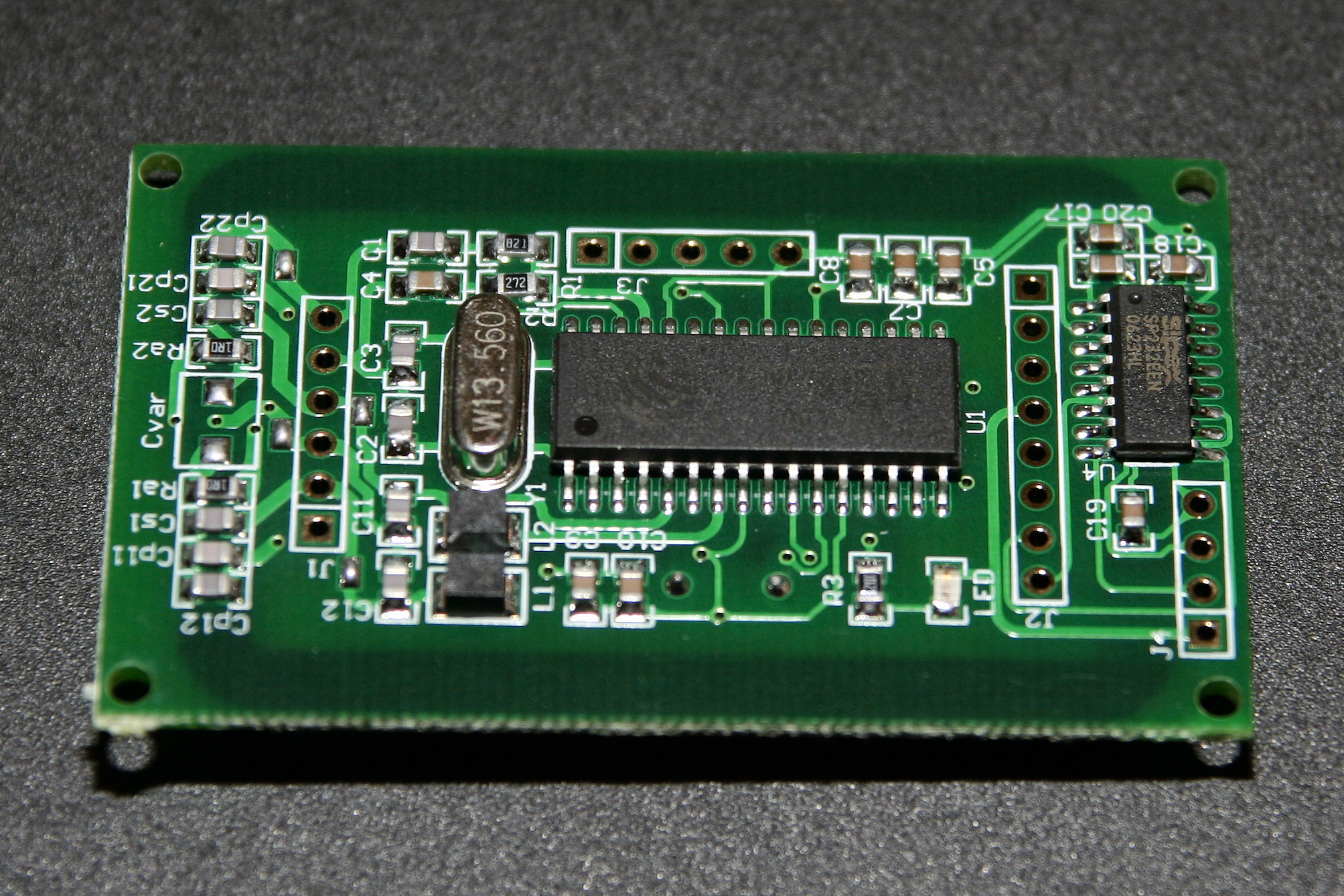
Parts List (And Digikey Part#): [Might need updating for v1.1?]

  • C1, C2: CAP TANTALUM 4.7UF 10V 20% SMD (511-1491-1-ND)
  • C3, C7: CAP CER 1UF 25V X5R 0603 (490-3897-1-ND)
  • C4-6,C8-13: CAP CER .1UF 25V 10% X7R 0603 (490-1524-1-ND)
  • C14, C15: CAP CER 18PF 50V C0G 5% 0603 (445-1272-1-ND)
  • C16: CAP CER 3.3UF 10V X5R 0603 (445-5168-1-ND)
  • U1: IC REG LDO 3.3V 250MA SOT-23A (MCP1702T-3302E/CBCT-ND)
  • U2: IC EEPROM 1KBIT 2MHZ SOT23-6 (93LC46BT-I/OTCT-ND)
  • U3: IC USB UART/MPSSE QUAD HS 64LQFP (768-1026-1-ND)
  • U4: CRYSTAL 12.0000 MHZ 18PF SMD (535-9836-1-ND)
  • R1, R3, R4: RES 10K OHM 1/10W 1% 0603 SMD (RMCF1/1610KFRCT-ND)
  • R2: RES 2.2K OHM 1/10W 1% 0603 SMD (RMCF1/162.2KFRCT-ND)
  • R5: RES 1K OHM 1/10W 1% 0603 SMD (RMCF1/161KFRCT-ND)
  • R6: RES 12.0K OHM 1/10W 1% 0603 SMD (311-12.0KHRCT-ND)
  • L1, L2: FERRITE 1A 60 OHM 0603 SMD (240-2370-1-ND)

Schematic:

v1.1 as attached. NB, it was made with gEDA, not Eagle.

PCB Layout:

v1.1 as attached. NB, it was made with gEDA / PCB, not Eagle.

Suggestions:

All suggestions are welcome. Please leave a comment below to let me know what you think, or if you have any feature requests.

License:

This project is released under the CC BY-NC-SA 3.0 license. If you wish to use this project for commercial purposes, please contact me.

Availability:

I have a number of v1.1 boards available. I will be able to put one together for testing/debugging once I get parts for it. Unfortunately, the high-accuracy, small-form-factor crystal is backordered until something like November (2010).

Disclaimer:

This is for educational purposes only. I’m not liable for damages caused to you or your property (including but not limited to netbooks).

What I would buy/bought with $100 at SparkFun Electronics

What I would buy/bought with $100 at SparkFun Electronics

Since SparkFun Electronics announced Free Day on January 7, 2010, I figured I’d start looking at what exactly I could get for $100. (I’ll only link the big items for risk of being called Spam by Googlebot.) This list is a work in progress, I’ll add more as I search.

To anyone new to electronics, I would suggest the Arduino (See arduino.cc for more information).

Idea 1: Oscilloscope kit and soldering supplies (Probably better to get the Oscilloscope Kit at Seeed Studios for $33)

  • Digital Oscilloscope Kit $45.95
  • BNC probe kit $12.95
  • 9V DC/350mA power supply $5.95
  • Soldering Iron Stand $5.95
  • Brass Sponge $2.95
  • Diagonal Cutters $1.95
  • Total: Not quite done yet!

Idea 2: Reflow toaster controller kit and swag

  • Reflow Toaster Controller $89.95
  • SparkFun Pint Glass ($9.95) OR (SFE Iron-on patch ($4.95) and SparkFun Coffee Mug ($4.95)) OR Sparkfun Projects Case (Clear) ($11.95)
  • Total: $99.85 or $99.90 or $101.90

Idea 3: 3pi Robot (Probably better to get the 3pi at the Maker Shed, since their 3pi bundle is on sale for the same price, and use the free $100 to get other stuff)

  • 3pi Robot $99.95
  • Total: $99.95

Idea 4: Eee PC Hacking (NO. These modules’ antennae are too big for the Eee. A separate GPS with panel-mount SMA would be better.)

  • 20-Channel GS405 (SiRF Star III chipset) or 50-Channel GS407 (u-Blox 5H chipset) Helical GPS Receiver. Either is $89.95.
    (People have been having problems getting GPS to work right when put inside the EEE 700/701/702, but they’ve been trying to use a ceramic antenna instead of a helical one. Maybe helical is the answer?)
  • Surface-mount connector to fit the above. For GS405, $0.95. For GS407, $1.25
  • Total: $89.95+ (or maybe more Eee hacking stuff)

Idea 5: Uber Eee PC Hacking

  • UFl to RP-SMA Connector for external wifi antenna, $4.95 (Plus antenna, $7.95-$9.95) (Sold out for now, i’ll leave it alone)
  • Arduino Pro Mini 328, $18.95 (3.3V version or 5V version) OR Breakout Board for PIC24HJ64 – Mini Bully, $19.95 (3.3V) (Though neither have the serial to usb converter onboard… They would require something like the FTDI Basic Breakout, $13.95)… Maybe I should just make my own from a USB-capable PIC SOIC board?)
  •    OR… Just use an FT2232 chip to do all the controlling! (I’ll custom-build a circuit board based on FT2232 and a latch to control the innards of the Eee… Power switching to various devices, spi expander for sensors, etc)
  • FM Receiver Breakout Board – AR1010, $14.95 (Hmm, not RDS-capable…)
  • Triple Axis SPI Accelerometer Breakout – SCA3000, $44.95 (Temperature compensating, voltage regulated, input 3.35V-10V) OR Triple Axis Analog Accelerometer Breakout – ADXL335, $24.95
  • Total: $?+

Idea 6: Soldering Station

  • Soldering Station Variable Temperature 70W – Digital, $99.95
  • And maybe a smaller tip (each $14.99)
  • Total: $99.95+

Subtotal: GPS (Idea 4) + Uber Eee PC Hacking (Idea 5)

Seiko/Epson RG9013F-NZ LCD Screen

Seiko/Epson RG9013F-NZ LCD Screen

I got this LCD screen free with one of my computer-related eBay purchases.

The label on the bubblewrap says:

Seiko/Epson RG9013F-NZ VGA 640×480 Mono for Dragonball EZ
Used/Excellent – Full Factory Spec Sheet At:
www.openhardware.net/ez328simm/resources.html [archive.org link]

Spec Sheet [PDF, archive.org link]

According to store.earthlcd.com, the EG9013FNZ1 is an STN Passive Transmissive 6.3″ 640×480 Monochrome LCD display with a CCFL backlight.

POM PPM Parking Meter

POM PPM Parking Meter

I found this parking meter at Princess Auto yesterday. Made by POM Inc., this meter is called the PPM.

I got it to work by adding a rubber band with just enough tension to depress the turn-detect lever when the lever is turned. The meter has knobs where a tensioned spring was attached. I’ll have to find a decent spring somewhere.

Opening it up, I found that the coin detector uses a series of armatures and four switches to detect which coin was inserted.

Upon examination, it has 6 buttons:

  • (Top Left) Yellow button for debug output
  • (Bottom Left) Yellow button for turn-sense
  • White buttons (4) for coin sense

When a Quarter is inserted into the proper slot and the arm is turned…

  1. As the coin lever is turned, the turn button is pressed.
  2. As it passes the buttons, the quarter makes the arm hit all 4 white buttons, in a clockwise order starting with the top left.
  3. When the turn lever is released, it returns to its original position, and releases the turn button.

When a Dime is inserted into the proper slot and the arm is turned…

  1. As the coin lever is turned, the turn button is pressed.
  2. As it passes the buttons in a clockwise order starting with the top left, the quarter makes the arm skip the first white button, and hits the remaining 3 white buttons.
  3. When the turn lever is released, it returns to its original position, and releases the turn button.

When a Nickel is inserted into the proper slot and the arm is turned…

  1. As the coin lever is turned, the turn button is pressed.
  2. As it passes the buttons in a clockwise order starting with the top left, the quarter makes the arm skip the first 2 white buttons, and hits the remaining 2 white buttons.
  3. When the turn lever is released, it returns to its original position, and releases the turn button.

When you press the Debug button, the front LCD shows the following:

  1. Test pattern: “c2:2c”, where the last ‘c’ is backwards.
  2. Firmware Version?: “0159”, also the number writen on a sticker on top of the ST27C256
  3. Parking Limit: “0002”, maximum number of hours allowed to park
  4. Route?: “0321”, also printed on a sticker on the back of the meter. This was the same for other meters i saw.
  5. Unknown: “8:5”, “8:6”

Interesting innards:

LCD/LEDs

  • LCD1: LCD, Front: 4-digit, “88:88” LCD
  • LCD, Back: Red, Clear background. No text.
  • D3: Red LED, (clear casing)
  • D4: IR LED
  • D5: IR Sensor

Switches

  • SW5,6: Yellow Switches (Surface mount)
  • SW1,2,3,4: White Switches (Surface mount)

ICs

  • U6: Motorola MC14519B – Four bit AND/OR selector
  • U2: Motorola MC14521B –
  • U7: Motorola MC145453FN – LCD 33-Segment LCD Driver, Serial, CMOS
  • U5: Motorola MC68HC11A1FN – Motorola 8-bit Microcontroller, 256 Kbit RAM, A/D converter, EEPROM
  • U4: Fairchild MM74HC373WM

    – 3-STATE Octal D-Type Latch

  • U3: THMOS ST27C256 – 256Kbit (32Kx8) CMOS 3-STATE (UV-Erasable?) EPROM
  • U1: 271BC – Programmable Low-Power OP-Amp
  • U8: Motorola HC20 – Dual 4-input NAND gate
  • U9: 74HC02M – Quad 2-Input NOR Gate

Headers

  • J2: 4-pin header
  • JP4, JP3, JP2, JP1: Jumpers, unpopulated, to ground certain pins on U5

See also:
http://www.globalnerdy.com/2008/07/17/rubyfringe-guide-active-surplus-aka-hardware-nerdvana/
Pics in action:
http://www.sonomatlc.org/Parking/PBDs/Pkg_Benefit_Districts.htm
http://www.dkimages.com/discover/DKIMAGES/Discover/Home/Geography/North-America/United-States/Travellers-Needs/Practical-Information/Transportation/Roads/Chicago/Parking-Meter/Parking-Meter-1.html

RFIDGeek/Univelop RF500B RFID Module

RFIDGeek/Univelop RF500B RFID Module

This is the RFID Module sold by RFIDGeek/Univelop Tech. While this little module might not look like much, it IS true what they say, “Good things come in small packages”.

By wiring +5 and Ground, as well as RS232 RX and TX to the board, you can use the included program to read and write to/from MiFare cards.

The company website (RFIDGeek.com) does not do the module justice. This little ~1.35″*2.25″ RFID reader/writer module packs the following onboard:

Top Side:

  • Fudan Microelectronics FM1702NL (32-pin SOP): [PDF] Parallel or SPI Interface (Note, the higher models, FM1715NL and FM1725NL both share a common pinout, and offer increased features [see the PDF]. I wonder if the board would work with one of these instead of the FM1702…)
  • 13.56Mhz Crystal
  • Sipex SP232EEN: TTL-RS232 Converter

Bottom Side:

  • LSI 1021WI?: (8-pin SOP, bottom side of the module)
  • Unknown Microcontroller: (44-pin, ID has been shaved off)
  • 11.0592Mhz Crystal

There is space available to add pin headers to the board for each of the following: (All of these are subject to change and/or verification)

J1: Antenna Interface

  1. Ground
  2. Transmitting Antenna 1
  3. Ground
  4. Transmitting Antenna 2
  5. Ground
  6. Receiving Antenna

J2: Microcontroller Interface

  1. Control Output
  2. Buzzer Output (High)
  3. RS485 Control (Low)
  4. VCC
  5. Reset Onboard MCU (High)
  6. Ground
  7. UART Receive
  8. UART Transmit

J3: Microcontroller SPI? (For the “Module 500” Only?)

  1.  
  2.  
  3.  
  4.  
  5. SPI Clock Out from FM1702NL Pin 24

J4: RS232 I/O

  1. VCC (+5V)
  2. RS232 Receive
  3. RS232 Transmit
  4. Ground
Targus RemoteTunes for iPod

Targus RemoteTunes for iPod

This is the Targus RemoteTunes(tm) for iPod. I got it from XSCargo, where they currently have them available for CDN$9.99.

Its guts include a transmitter and receiver pair. Even considering I don’t have an iPod to use this with, for $10.. I’m not arguing.

The receiver has:

The transmitter has:

The receiver and transmitter both have some unused pins on them:

Receiver (Base):

  • J: ICSP Data 
  • C: ICSP Clock
  • V: VPP / !MCLR
  • G: Ground
  • +: 3.3V from iPod

    PIC Pins:

  1. Power (Vcc = 3.3V)
  2. ?
  3. (Something to do with the output jack)
  4. VPP (Programming Voltage) / !MCLR (Reset)
  5. Data (From HiMark Pin 8)
  6. ICSP Clock
  7. ICSP Data / Serial Transmit
  8. Ground

    HiMark Pins: (Pages 11-12 of Datasheet. Pins I especially care about are un-italicized.)

  1. Oscillator 2 (From Tunable Coil)
  2. IF filter output
  3. Comparator input A
  4. Comparator input B
  5. Comparator offset adjustment
  6. Ground
  7. Ground
  8. Data (to PIC Pin 5)
  9. Disable
  10. Comparator input C
  11. Limiter Input
  12. Limiter Feedback A
  13. Limiter Feedback B
  14. RF Amplifier Input (Virf)
  15. RF Amplifier Ground (Vee)
  16. RF Amplifier Output (Vorf) 
  17. Mixer Input
  18. Power (Vcc = 3.3V)
  19. Power (Vcc =.3.3V)
  20. Oscillator 1 (To Tunable Coil)

Transmitter (Remote):

  • J: VPP / !MCLR
  • C: Serial Programming Clock
  • Unlettered: Serial Programming Data
  • G: Ground
  • +: Batteries (6V)

    PIC Pins:

  1. Power (Batteries)
  2. ?
  3. Play/Pause Button (Center)
  4. VPP (Programming Voltage) / !MCLR (Reset)
  5. Volume Down (Bottom Left)
  6. Volume Up (Bottom Right)
  7. ?
  8. LED
  9. ?
  10. Crystal?
  11. ?
  12. Serial Programming Clock / Back Button (Top Left)
  13. Serial Programming Data / Forward (Top Right)
  14. Ground 

See also:
Apple iPod Jack Pinout – Explains the pinout and protocol for 2nd and 3rd Generation iPods.

(iPod is a trademark of Apple Computer, Inc.)

Anadigi GPS-R02 DIY GPS Kit

Anadigi GPS-R02 DIY GPS Kit

I got this little “Anadigi GPS-R02 DIY” car gps kit from eBay seller anadigi-hk, and it was mailed direct from Hong Kong.

[Edit: Apparently, the eBay Store and user are no more.]

It came with the GPS Circuit board and a little plastic case for it, an MMCX antenna with magnetic base, and a matching USB cable. The mini-CD came with drivers and a few test and diagnostic programs.

It works great; by the time my computer comes out of hibernation, it already has a signal lock. Talk about bang for the buck!

The receiver is based on the NemeriX NJ1030A [Datasheet – Archive.org], and includes WAAS/EGNOS support.

Markings on the box: (They look like the vitals for the GPS Antenna)

  • Product Model: GPS
  • Center Frequency: 1575.42 +/-3Mhz
  • LNA Gain (Without Cable): 28dB
  • Noise Figure: <1.5dB
  • VSWR: <2.0
  • DC Current: 10mA Max
  • Mounting: Magnetic Base
  • Housing: Black
  • Working Temp: -40*C ~ +85*C
  • Vibration: Sine sweep lg(0-p) 10~50~10Hz each axis
  • Humidity: 95%-100%RH
  • Weatherproof: 100% Weatherproof
  • Cable Length: 3m
  • Voltage: 3-5V
  • Connector: MMCX
  • USB to Serial Converter (onboard): PL-2303* (but the Prolific Windows driver doesn’t like it, errors with Code 10: Cannot start”, according to the Prolific website, that means it’s likely a counterfeit PL-2303 chip. I’ll have to dig out the CD that came with it again.)

Update: How to add GPS to your Eee PC @ beta.ivancover.com – That’s definitely one of the first things I’d do with an Eee.

Sharp LQ13X02C

Sharp LQ13X02C

Ok, this 13″ Sharp TFT LCD screen with XGA (1024×768) resolution was used in some Dell and NEC laptops, including the Dell Latitude CPi D266XT.

The Dell Latitude’s screen and inverter has a connector to the motherboard consisting of 50 pins (25 x 2 pins)

Motherboard Connector [LVDS connector?]:

1. ?      26. ?
2. ?      27. ?
3. ?      28. ?
4. ?      29. ?   
5. ?      30. ?
6. ?      31. ?
7. ?      32. ?
8. ?      33. ?
9. ?      34. ?
10. ?    35. ?
11. ?    36. ?
12. ?    37. ?
13. ?    38. ?
14. ?    39. ?
15. ?    40. ?
16. ?    41. ?
17. ?    42. ?
18. ?    43. ?
19. ?    44. ?
20. ?    45. ?
21. ?    46. ?
22. ?    47. ?
23. ?    48. ?
24. ?    49. ?
25. ?    50. ?


CCFL Inverter Connector:

1 & 2. ?
3. ?
4. ?
5. ?
6. ?
7. ?
8. ?
9 & 10. ?

Sharp LCD Connector:

  1. [Top of LCD] ?
  2. ?
  3. ?
  4. ?
  5. ?
  6. ?
  7. ?
  8. ?
  9. ?
  10. ?
  11. ?
  12. ?
  13. ?
  14. ?
  15. ?
  16. ?
  17. ?
  18. ?
  19. ?
  20. [Bottom of LCD] ?