Browsed by
Category: Routers

My Router-based projects, including the (in)famous WRT54

Domino.io Module Tips and Tricks

Domino.io Module Tips and Tricks

Some basic instructions/ramblings to get started (as the documentation for the Domino module isn’t currently complete)

To connect your Domino to a WiFi network using a GUI:

Plug in your Domino Pi/Qi/base module and use your phone or laptop to connect to the “Domino-***” Wifi. The default password is “goodlife”. Navigate to http://192.168.1.1/ to access the web interface. Change your device’s hostname and password on the web interface and click “Okay, Reset”. Reconnect using your new password, navigate again to http://192.168.1.1/ and log in using your new password, and you will have access to the web interface.

The basic interface (“Domino Web Panel”) is mobile-friendly; the “LUCI” tab, however, is still formatted for larger screens.

To connect to your local wireless network, choose “LUCI”, then “Network”, “WiFi”. Click “Scan” beside “Generic Wireless” and click “Join Network” next to your WiFi. Enter your password and hit “Submit”. Scroll to the bottom of the page and select “Save and Apply”. You can now access http://domino.local/ from your network.

To connect your Domino to a WiFi network using the command line:

Connect your domino by USB and open a terminal to it (/dev/ttyUSB0 on Linux or whichever COM port Windows assigns) at 115,200 bps. You will have root access just like any OpenWRT implementations. You will want to change the wifi-iface block in /etc/config/wireless to look something like the following (modify to suit your needs):

config wifi-iface
option network ‘wwan’
option ssid ‘yourwifinamehere’
option encryption ‘psk2’
option device ‘radio0’
option mode ‘sta’
option bssid ‘ma:ca:dd:re:ss:he:re’
option key ‘yourpasswordhere’

Mount points / Storage:

With the 3x USB + MicroSD expansion:
/mnt/sda1 is your microSD card
/mnt/sdb1 is your USB,
/mnt/sdc1 is your internal Flash storage

Getting a terminal on the Domino Qi (Arduino Yun Clone):

  1. Upload the YunSerialTerminal sketch over USB
  2. Connect to the Qi at 115200 8N1 and send ~2 to set it to 115200 (Otherwise you’ll just get garbage)

More goes here as I play around with it…
WiiMu A01 (Work in Progress)

WiiMu A01 (Work in Progress)

This is an information dump of the WiiMu A01 in hopes of instituting audio control with the OpenWRT firmware.

PCB Silkscreen:

MVSILICON& WiiMu A01 V2.0 2013.03

Default firmware:

Kernel:

Busybox Linux 2.6.21, built from the Ralink SDK

Modules:

printk, 8250, rt_rdm, rt2860v2_ap, block2mtd, ohci_hcd, snd_timer, snd_seq_oss, snd_soc_core, nf_nat_ftp, rcupdate, rd, ppp_async, scsi_mod, usbcore, usb_storage, snd_pcm, snd_seq, nf_conntrack, iptable_filter, n_hdlc, loop, pppopptp, sg, ehci_hcd, snd, snd_pcm_oss, snd_seq_dummy, nf_conntrack_ftp, tcp_cubic

Libs:

  • libintl.so
  • libresolv-0.9.28.so
  • libintl-0.9.28.so
  • libnsl-0.9.28.so
  • libuClibc-0.9.28.so
  • libpthread.so
  • libnsl.so
  • libcrypt.so
  • libm-0.9.28.so
  • libnvram.so.0
  • libintl.so.0
  • libupnp.so.1.3.1
  • libutil-0.9.28.so
  • libm.so
  • libntfs-3g.so.26
  • libutil.so.0
  • libresolv.so
  • libcrypt-0.9.28.so
  • libc.so
  • libdl-0.9.28.so
  • libutil.so
  • libiw.so.29
  • libixml.so.1.3.1
  • libcrypt.so.0
  • libm.so.0
  • libnvram-0.9.28.so
  • libc.so.0
  • libdl.so
  • libnvram.so
  • libnsl.so.0
  • libdl.so.0
  • libthreadutil.so.1.3.1
  • libpthread-0.9.28.so
  • ld-uClibc-0.9.28.so
  • libpthread.so.0
  • libresolv.so.0
  • ld-uClibc.so.0
  • 2.6.21/kernel/drivers/net/wireless/rt2860v2_sta/rt2860v2_sta.ko
  • 2.6.21/kernel/drivers/char/hw_random/rng-core.ko

Unpacking the root_uImage upgrade:

Using binwalk, specifically

binwalk -Me root_uImage

I was able to extract the root_uImage

Audio DAC

My unit had the DAC markings sanded off, but from /proc/asound/cards, DAC appears to be an Everest Semiconductor ES8155. According to their product sheet, it is a 2-channel DAC in QFN-28 package.

  • SNR: 96 dB
  • THD+N: -85 dB
  • Headphone Amp: Yes
  • Line Driver: Yes
  • PLL: Yes
  • Additional Function: 3-band PEQ
  • Supply Voltage: 1.5 to 3.6 V
  • Low Power: 7 mW
OpenWRT on the DIR-615 Rev. A1 (Marvell 88F5181L) [Work In Progress]

OpenWRT on the DIR-615 Rev. A1 (Marvell 88F5181L) [Work In Progress]

This article will document the process of making OpenWRT work on the DIR-615 rev. A1.

In its dmesg, the stock firmware reports this board as “Marvell Development Board (LSP Version 0.0.102)– RD-88F5181L-VOIP-FE”.

In the GPL’d source code available from D-Link [FTP], in DIR-615A1-GPL.tgz (inside the downloaded file), in Noahsark/platform/MVL5181/linux/arch/arm/mach-mv88fxx81/Board/boardEnv/DB_88FXX81/mvBoardEnvSpec.h, a search for “RD-88F5181L-VOIP-FE” reveals a list of constants that pertain to the board. (See attached .XLS file)

I created Board ID# 4262 at the ARM Linux website to describe this board.(This document from Nas-Central.org explains why this needs to be done, and goes into detail about how to get support for your particular Orion board type in the mainline Linux kernel. This only ever needs to be done once for each type of board defined on the ARM Linux site, so consider it “already done” for the D-Link DIR-615 and/or the Marvell RD-88F5181L-VOIP-FE reference board.)

Update (25-Jul-2012): I just received my Dangerous Prototypes Bus Blaster to allow me to use JTAG with either OpenOCD or urjtag, among others. It seems that the resistor and capacitor footprints beside the JTAG header need to be populated to allow JTAG access. Proper SMD resistors and caps are part of my next DigiKey order.

Unbricking a D-Link DIR-615 Rev A1

Unbricking a D-Link DIR-615 Rev A1

I have managed to unbrick a D-Link DIR-615 Rev A1 back to D-Link firmware (1.00) from firmware 1.10. Allow me to describe the situation:

  • Given a direct connection to my laptop, the router does not respond to HTTP requests on either WAN or LAN, does not assign DHCP IP addresses, cannot ping or respond to pings, but does show up on the laptop in the ARP tables (arp -an). (This same setup has worked for numerous non-bricked routers, so it seems that some busybox functionality is corrupt.)
  • Over serial, the uBoot bootloader cannot connect to a TFTP server (and does not have the ability to flash over serial).

Attached to this article is a log of one of these so-called “failboots”. It can be easily identified as it only one block of text following the BusyBox ash shell:

BusyBox v1.1.0 (2007.07.26-06:29+0000) Built-in shell (ash)
Enter 'help' for a list of built-in commands.
/ # pc : [<40146968>] lr : [<400ca0b8>] Not tainted
sp : befaf8a0 ip : 00000002 fp : 40079bf8
r10: 00000003 r9 : 40079bb8 r8 : 00050500
r7 : befb5c75 r6 : 00026740 r5 : befb5c74 r4 : 0002674a
r3 : 00000065 r2 : 0000000a r1 : 00026741 r0 : 400ca0b7
Flags: nzCv IRQs on FIQs on Mode USER_32 Segment user
Control: A005317F Table: 01DF0000 DAC: 00000015

A successful bootup (log also attached) is followed by much more serial chatter, such as bringing up interfaces, mounting flash, etc.

BusyBox v1.1.0 (2007.01.24-07:26+0000) Built-in shell (ash)
Enter 'help' for a list of built-in commands.
/ # cp -f /etc/nvram.default /var/etc
mount -t jffs2 /dev/mtdblock2 /flash
cp -f /flash/nvram.conf /var/etc
brctl addbr br0
brctl stp br0 off
brctl setfd br0 0
brctl addif br0 eth1
device eth1 entered promiscuous mode
[... etc ...]

To recover your device:
(Warning: This might damage your device; however, if you are in need of these instructions, I don’t think it’s possible to damage it any more.)

1) Solder on serial headers to CON5 (on the side opposite of the mini-PCI slot)

2) With an Ethernet cable, connect the DIR-615’s WAN port to one of the LAN ports of another router, as it doesn’t play well otherwise. (It seems to need an intermediary to handle ARP tables for it while bricked like this)

3) Power it on, let it boot up, and over the serial connection to the router, run “ipconfig eth0 192.168.1.25” or some other memorable IP address that’s in the same subnet as your computer

4) Again, over serial connection to the router, run “tftpd”

5) On your computer, download the firmware from DLink: ftp://ftp.dlink.com/Gateway/dir615/Firmware/dir615_firmware_100.bin

6) And with a tftp client (See Installing OpenWRT via TFTP (Bootloader contains TFTP Server)), upload the .bin file to the router.

The router will flash itself, then reboot, and erase the (dirty) NVRAM. It will set itself to the default 192.168.0.1.

The key, I believe, lies in installing a version of firmware that is not currently installed, so as to erase all NVRAM settings. If you try to reinstall the same firmware, it will not clear the device’s (faulty) settings. In other words, there may be a much easier way to debrick the device, however with the limited (and possibly corrupt) BusyBox commands, I took the first viable option I could get.

I hope this works for you as it did for me, but as usual, ‘no promises’.

How to convert .RMT to .BIN for OpenRG Bootloader (RGLoader)

How to convert .RMT to .BIN for OpenRG Bootloader (RGLoader)

I recently encountered a situation while loading firmware into an Actiontec MI424-WR router, when I found myself without a bootable firmware, and the OpenRG bootloader would vehemently refuse to load .rmt files.

The MI424-WR has two sections in its Flash for firmware. The stock firmware available from Actiontec is, of course, a RMT. (I did in fact have the .bin dump of the entire flash chip, but I wasn’t about to attempt to make the bootloader overwrite itself.)

After comparing hex dumps, I came to the conclusion that .rmt files are .bin files with a 148-byte header. All you have to do to create a .bin that is ready to be downloaded by the router is to use the following command:

dd if=firmware.rmt of=firmware.bin bs=1 skip=147

Such that the resulting “firmware.bin” file begins with 0xE2 0x8F 0xA0 like other .img files built for this router. I’m not sure if the “magic” will be the same for other machines, but that’s what it seems to be for the MI424-WR running on the stock bootloader (OpenRG).

I hope this saves someone some hassle. As usual, no guarantees of accuracy or completeness 😉

WIP: DIR-615 rev C1 Hacking

WIP: DIR-615 rev C1 Hacking

In my most recent thrift store trips, I found (among other things) a large quantity of D-Link DIR-615 Rev C1.

Some relevant linkage:

Things on my TODO List:

  • Add a USB port and/or hub, and supporting components
  • Add a third antenna (requires a lot of supporting components)
  • Install Kismet and gpsd for a mobile wardriving box?
  • Add I2C Bus over GPIO
  • Add SD Card Support over GPIO?
WIP: Cantenna

WIP: Cantenna

This shows step by step how I made a Cantenna. This is a simplified tl;dr version of “How to build a tin can waveguide antenna” by Gregory Rehm.

Materials:

  • 1x Can, washed (hapi HOT Wasabi Peas [450g])
  • 1x N-type, Female Chassis-mount connector (Digikey# 367-1081-ND)
  • 1x Piece of copper wire
  • 4x Nuts & bolts

Prep:

  1. Measure diameter of the can -> 3.9″
  2. Calculate wavelength using waveguide calculator found here.
  3. Mark a point 1/4 Wavelength up from the bottom (closed) side of the can.
  4. Measure the hole to be cut (diameter of part of the connector that will be going inside the can) -> 0.43″
  5. Drill marked point to measured diameter (0.43″)
  6. Dry-fit the connector, and mark holes for the screws or nuts/bolts (if any)
  7. Drill marked points to the diameter of your connector’s holes (if any)
  8. Cut a piece of copper wire so that when it is in the copper sleeve on the connector, the total length of the copper sleeve and piece of copper is exactly 1.21″ (or as close as you can humanly get to it), and solder it in place.
  9. Mount the connector in the hole in the can and secure it with screws or nuts/bolts (if any). Make sure to mount the heads of the screws or bolts inside the can to reduce antenna obstruction.
WRTSL54GS Hardware & Architecture

WRTSL54GS Hardware & Architecture

Here’s the dump of /proc/cpuinfo:

# cat /proc/cpuinfo
system type             : Broadcom BCM4704 chip rev 8
processor               : 0
cpu model               : BCM3302 V0.6
BogoMIPS                : 263.78
wait instruction        : no
microsecond timers      : yes
tlb_entries             : 32
extra interrupt vector  : no
hardware watchpoint     : no
VCED exceptions         : not available
VCEI exceptions         : not available

Here’s the dump of /proc/interrupts:

# cat /proc/interrupts
           CPU0
  2:      26752            MIPS  eth2, ehci_hcd
  3:        223            MIPS  serial
  4:       2476            MIPS  eth0
  7:      95322            MIPS  timer
ERR:          0

Here is the dump of /proc/pci:

# cat /proc/pci
PCI devices found:
  Bus  0, device   0, function  0:
    Class 0501: PCI device 14e4:0800 (rev 8).
      IRQ 3.
      Non-prefetchable 32 bit memory at 0x18000000 [0x18000fff].
      Non-prefetchable 32 bit memory at 0x1fc00000 [0x1fffffff].
      Non-prefetchable 32 bit memory at 0x1c000000 [0x1dffffff].
      Non-prefetchable 32 bit memory at 0x1a000000 [0x1bffffff].
  Bus  0, device   1, function  0:
    Class 0200: PCI device 14e4:4713 (rev 8).
      IRQ 4.
      Master Capable.  Latency=64.
      Non-prefetchable 32 bit memory at 0x18001000 [0x18001fff].
  Bus  0, device   2, function  0:
    Class 0200: PCI device 14e4:4713 (rev 8).
      IRQ 5.
      Master Capable.  Latency=64.
      Non-prefetchable 32 bit memory at 0x18002000 [0x18002fff].
  Bus  0, device   3, function  0:
    Class 0c03: PCI device 14e4:4715 (rev 8).
      IRQ 6.
      Non-prefetchable 32 bit memory at 0x18003000 [0x18003fff].
  Bus  0, device   4, function  0:
    Class 0604: PCI device 14e4:0804 (rev 8).
      IRQ 2.
      Non-prefetchable 32 bit memory at 0x18004000 [0x18004fff].
      Non-prefetchable 32 bit memory at 0x8000000 [0xfffffff].
  Bus  0, device   5, function  0:
    Class 0b30: PCI device 14e4:0816 (rev 8).
      IRQ 2.
      Non-prefetchable 32 bit memory at 0x18005000 [0x18005fff].
  Bus  0, device   6, function  0:
    Class 0703: PCI device 14e4:4712 (rev 8).
      IRQ 2.
      Non-prefetchable 32 bit memory at 0x18006000 [0x18006fff].
  Bus  0, device   7, function  0:
    Class 1000: PCI device 14e4:4718 (rev 8).
      IRQ 2.
      Non-prefetchable 32 bit memory at 0x18007000 [0x18007fff].
  Bus  0, device   8, function  0:
    Class 0500: PCI device 14e4:080f (rev 8).
      IRQ 3.
      Non-prefetchable 32 bit memory at 0x18008000 [0x18008fff].
      Non-prefetchable 32 bit memory at 0x0 [0x7ffffff].
      Non-prefetchable 32 bit memory at 0x10000000 [0x17ffffff].
      Non-prefetchable 32 bit memory at 0x80000000 [0x9fffffff].
  Bus  1, device   0, function  0:
    Class 0600: PCI device 14e4:4704 (rev 0).
      IRQ 2.
      Master Capable.  Latency=64.
      Non-prefetchable 32 bit memory at 0x40000000 [0x40001fff].
      Prefetchable 32 bit memory at 0x0 [0x7ffffff].
  Bus  1, device   1, function  0:
    Class 0280: PCI device 14e4:4318 (rev 2).
      IRQ 2.
      Master Capable.  Latency=64.
      Non-prefetchable 32 bit memory at 0x40002000 [0x40003fff].
  Bus  1, device   2, function  0:
    Class 0c03: PCI device 1033:0035 (rev 67).
      IRQ 2.
      Master Capable.  Latency=8.  Min Gnt=1.Max Lat=42.
      Non-prefetchable 32 bit memory at 0x40004000 [0x40004fff].
  Bus  1, device   2, function  1:
    Class 0c03: PCI device 1033:0035 (rev 67).
      IRQ 2.
      Master Capable.  Latency=8.  Min Gnt=1.Max Lat=42.
      Non-prefetchable 32 bit memory at 0x40005000 [0x40005fff].
  Bus  1, device   2, function  2:
    Class 0c03: PCI device 1033:00e0 (rev 4).
      IRQ 2.
      Master Capable.  Latency=68.  Min Gnt=16.Max Lat=34.
      Non-prefetchable 32 bit memory at 0x40006000 [0x400060ff].
WRTSL54GS with new antenna

WRTSL54GS with new antenna

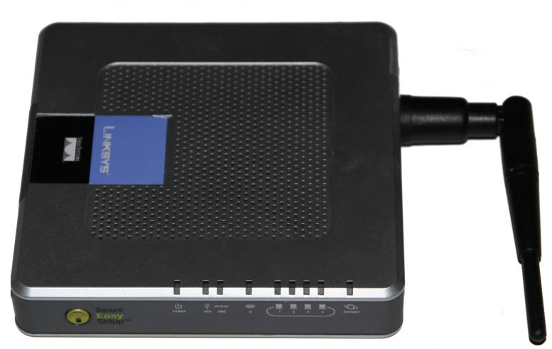
I desoldered the old, fixed antenna, and replaced it with a removable antenna.

I tested it out, and it works fine, if not better than the old one. Even though “better” is subjective, signal strength to my other router went from -87dBm to -53dBm, both with -99dBm noise.

Note, I had to mount the antenna in a different hole than the previous one, because there were parts in the way of the antenna mount.

WRTSL54GS Antenna Replacement

WRTSL54GS Antenna Replacement

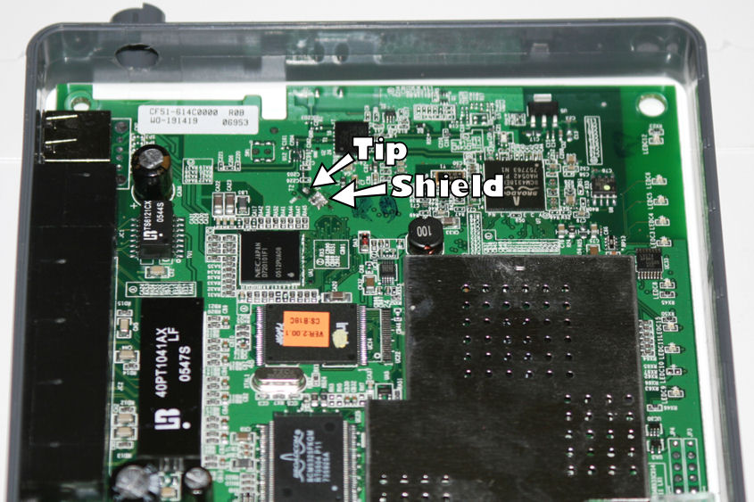
This photo shows you the location of the solder points for the antenna. The “tip”, or center of the antenna wire, is a little longer than the braided shield, and is soldered to the point marked “Tip”. The shield is just soldered together onto the portion marked “Shield”.

In other words, put it back in like you took it out, and make sure there’s no solder connecting the tip and shield parts. It tends to burn up your chipset. 🙂