WRTSL54GS Antenna Replacement

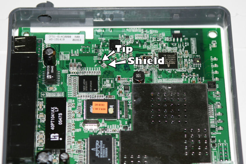
This photo shows you the location of the solder points for the antenna. The "tip", or center of the antenna wire, is a little longer than the braided shield, and is soldered to the point marked "Tip". The shield is just soldered together onto the portion marked "Shield".

In other words, put it back in like you took it out, and make sure there's no solder connecting the tip and shield parts. It tends to burn up your chipset. :)

WRTSL54GS Antenna Replacement
Image information
ModelCanon EOS DIGITAL REBEL XT
Focal Length90.0 mm
Exposure Time1/60 sec.
Aperturef/5.6
ISO Speed Ratings100
FlashFlash fired, compulsory flash mode.

Trackback URL for this post:

http://erroraccessdenied.com/trackback/803

Comments

Post new comment

The content of this field is kept private and will not be shown publicly.
  • Web page addresses and e-mail addresses turn into links automatically.
  • Allowed HTML tags: <a> <em> <strong> <b> <i> <u> <cite> <ul> <ol> <li> <dl> <dt> <dd> <blockquote> <br> <p> <img>
  • You may post code using <code>...</code> (generic) or <?php ... ?> (highlighted PHP) tags.
  • Textual smileys will be replaced with graphical ones.
  • You may quote other posts using [quote] tags.
  • Lines and paragraphs break automatically.

More information about formatting options

indeed