Neuros OSD – Top View
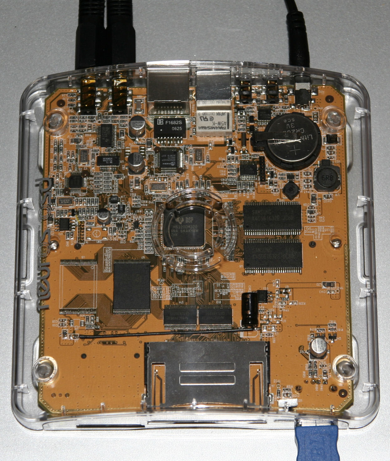
Here’s the top view of my new Neuros OSD. Here’s where you get to see all the goodies inside.
My Projects
Here’s the top view of my new Neuros OSD. Here’s where you get to see all the goodies inside.
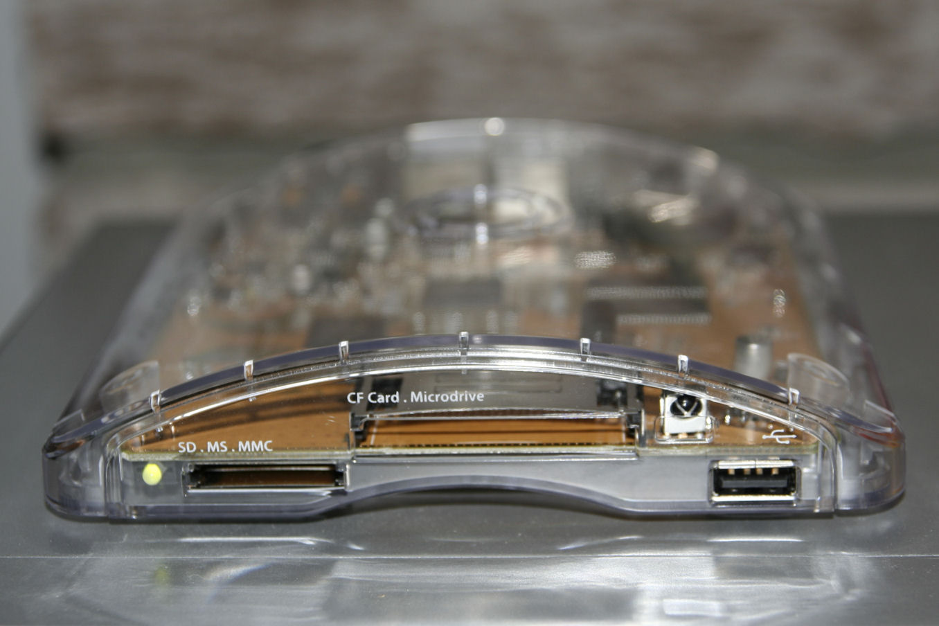
Here’s the view of the front of my new Neuros OSD.
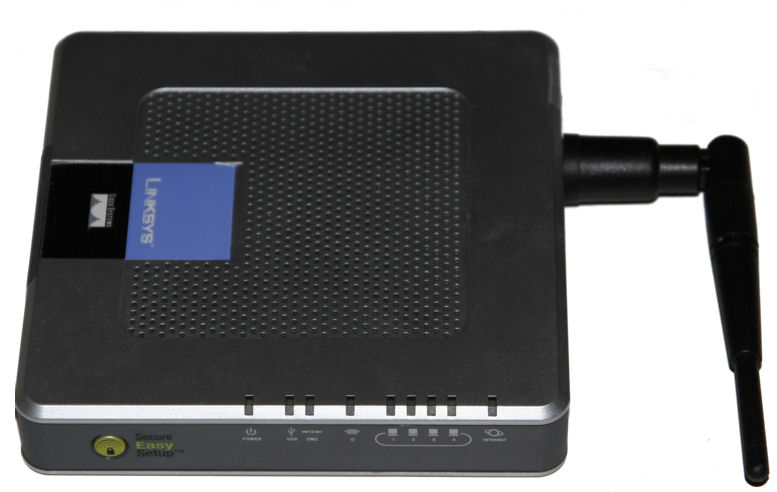
I desoldered the old, fixed antenna, and replaced it with a removable antenna.
I tested it out, and it works fine, if not better than the old one. Even though “better” is subjective, signal strength to my other router went from -87dBm to -53dBm, both with -99dBm noise.
Note, I had to mount the antenna in a different hole than the previous one, because there were parts in the way of the antenna mount.
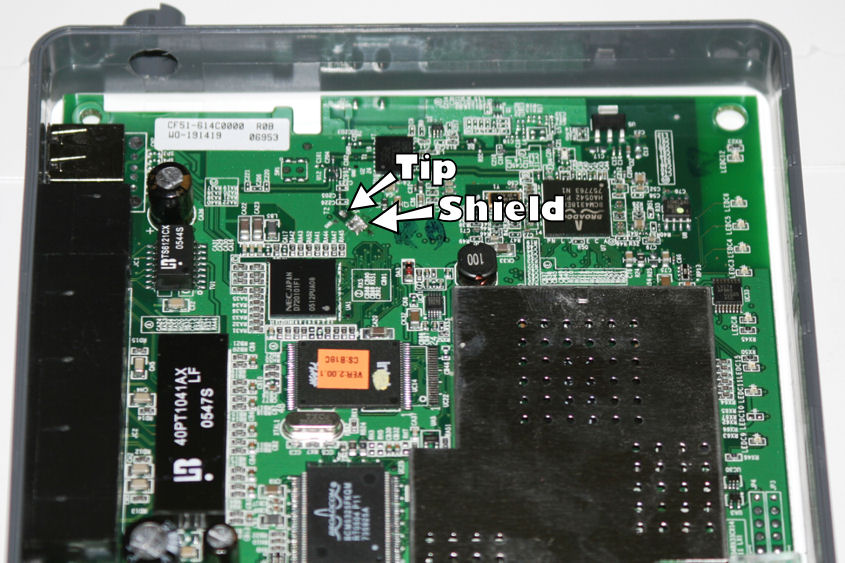
This photo shows you the location of the solder points for the antenna. The “tip”, or center of the antenna wire, is a little longer than the braided shield, and is soldered to the point marked “Tip”. The shield is just soldered together onto the portion marked “Shield”.
In other words, put it back in like you took it out, and make sure there’s no solder connecting the tip and shield parts. It tends to burn up your chipset. 🙂
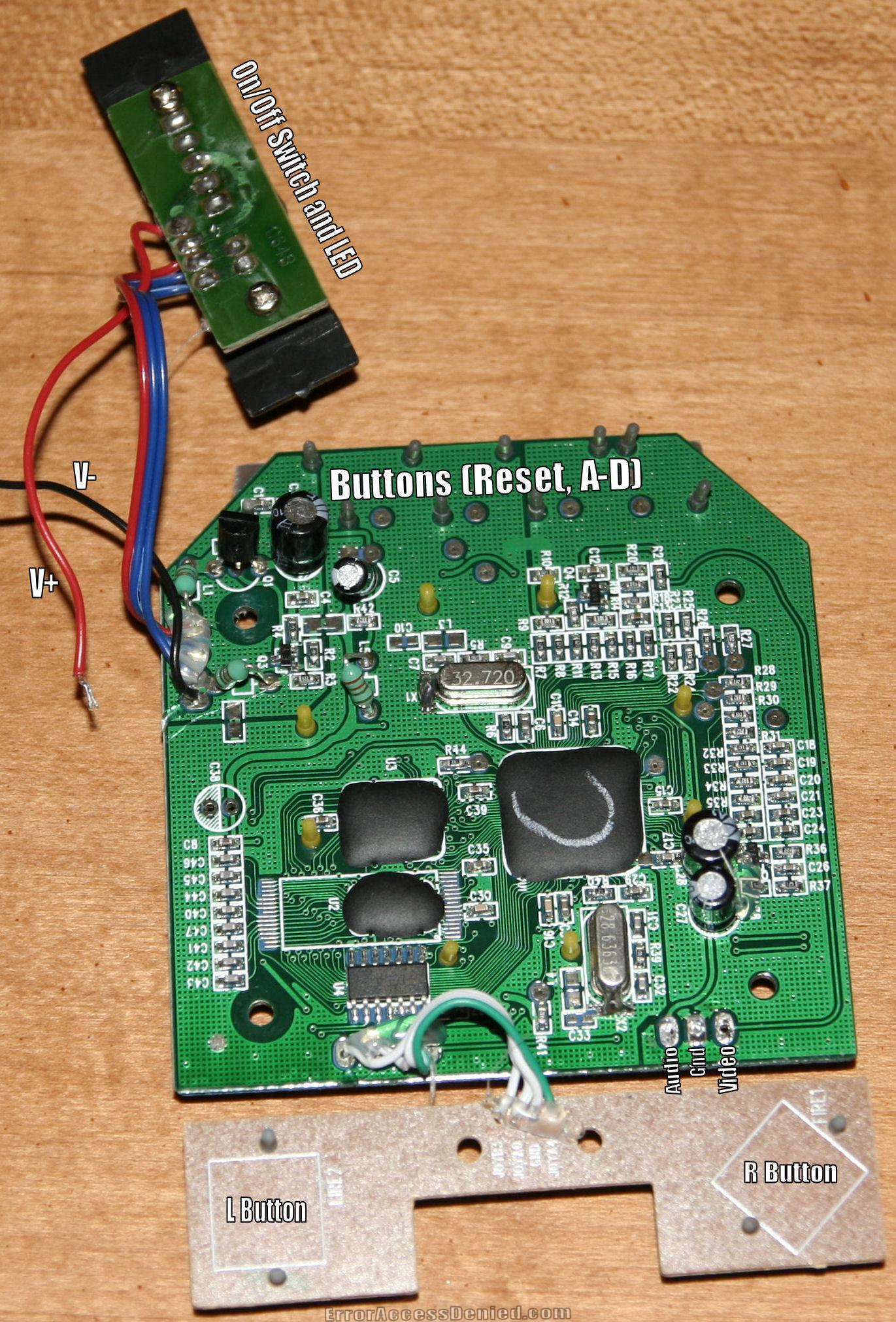
Here is the main PCB of the C64 DTV, along with the On/Off switch and Fire buttons, which have their own PCBs.
The positioning of the PCB is, of course, upside-down and backwards, but that’s OK.
The V+ and V- wires came from the V+ and V- connectors from the battery box on the lower portion of the joystick case. There is a large version available for your viewing pleasure by clicking the link below marked “original”.
For more great, high-res pictures of the various innards and assemblies, click out the VICUG Photo Gallery
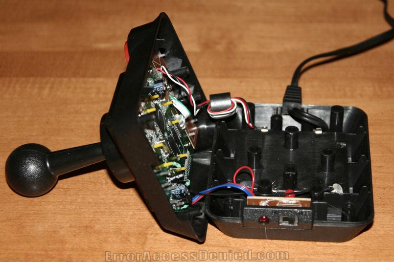
Ok, so I unscrewed it, but here’s the moment of glory!
4 screws on the bottom (Not under the rubber feet; in their own holes. Wow, this thing really WAS made for hacking) and it just pops open.
The power switch and LED just slide out of the bottom shell as one unit, the A/V cord pulls out too, and the only things left holding the bottom are the power wires. A quick zip with the desoldering iron fixed that problem.
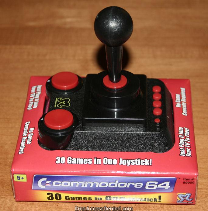
This is my new, snazzy Commodore 64 Direct-to-TV 30-in-1-games joystick. I ran it, played some games, now it’s time to hack it up!
The C64 Direct-to-TV, called C64DTV for short, is a single-chip implementation of the Commodore 64 computer, contained in a joystick with 30 built-in games. The design is similar to the Atari Classics 10-in-1 TV Game.
Tulip Computers (which had acquired the Commodore brand name in 1997) licensed the rights to Ironstone Partners, which cooperated with DC Studios, Mammoth Toys, and The Toy:Lobster Company in the development and marketing of the unit. [1] QVC purchased the entire first production run of 250,000 units and sold 70,000 of them the first day they were offered. Coincidentally, QVC’s West Chester, Pennsylvania Studio Park headquarters once were Commodore’s offices.
The circuitry of the C64DTV was designed by Jeri Ellsworth, a self-taught computer chip designer who had formerly designed the C-One.
Specifications:
The C64DTV runs on four AA batteries. It has two fire buttons, four function buttons, and composite video and monaural audio outputs. The internal hardware is a clone of the C64 and thus has the same features and limitations, but it lacks the keyboard and I/O ports. The internal circuit board has exposed solder points for floppy-drive and keyboard ports, and detailed instructions for adding them are available.
There are two versions of the C64DTV. The first appeared in late 2004 for the American market (NTSC television type), and has these features over the original C64:

These instructions are for any GM car with the 3100 engine, with air conditioning. (Engine code: M) These engines are found in the 1994-1996 Chevrolet Corsica, among other cars and years.
Some background info: The AC Compressor is held up with 3 LONG bolts. I’m not talking little things, I’m talking 4″ bolts.
About the picture: Here it is, upside-down. I’ve circled the part number of the compressor assembly in red. This is what you need to get yourself a new or used one. (IE, this is the number that carpart.com asks for)
I originally posted this article on Corsicas.com on January 18, 2006. To see original text, click here

These instructions are for a 1991-1996 Chevrolet Corsica, the instructions are similar for a pre-1991 Corsica, with the exception of the removal of the door panel.
Use an upholstery remover to take off the window crank (if you have crank windows). Note that there is a cotter pin holding the crank in place. You have to pull it off before the handle comes free.
Once the fixtures are free, the door panel can be pulled off. Don’t worry about giving it some force, the whole thing is just snapped on.
Once the rivots are removed, you can pull out the assembly (see picture) and fix what’s wrong.
In my case, the lock wasn’t locking, and it was because the lock part of it was siezed with rust. I gave it some WD40 to loosen it, and then slopped on some heavy grease.
I originally posted this article on Corsicas.com on December 6, 2005. To see original text, click here
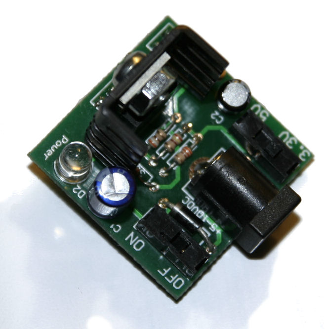
This is the finished product, after assembly of the Breadboard Power Supply.
For more info, see the First Post about it.